

Challenge
One of the major technologies to advance reduced carbon emissions is gasoline compression ignition (GCI) which has the potential to provide 50% thermal efficiency. GCI requires tight control of the fueling. An effective means to provide tight control is to utilize in-cylinder pressure measurement to analyze the combustion process. This process is used in engine control system development throughout the industry using expensive dedicated equipment such as piezo-electric pressure transducers and combustion analysis equipment. In the test cell this equipment has been shown to enable increases in efficiency, but the expensive lab equipment does not provide a path to field testing, prototyping or pre-production vehicle testing applications, or for that matter use in production.
Detroit Research Center of Aramco Services Company is a leading research facility working to improve Internal Combustion Engine (ICE) efficiency through GCI. “Aramco Services Company is committed to moving the energy industry forward by connecting people and partners in the Americas with our parent company, Saudi Aramco”. To demonstrate GCI in a field vehicle, Aramco Services Company needed complex cylinder pressure-based combustion calculations within the advanced engine control. It also needed to run in an ECU that could be applied to field testing in a production vehicle. Aramco Services Company also needed pressure sensors that could withstand the rigor of in-cylinder measurement. Sensors identified were the Sensata CPOS line used in high feature diesel engines.
Aramco Services Company determined the calculation required for control would include combustion heat release rates, peak pressure and max rate of pressure rise. These measures provide the means to determine efficiency of the combustion. For the control performance Aramco Services Company required these calculations to be completed before the beginning of the next engine cylinder cycle. Hence, the results can be used to adjust the injection and timing of the next engine cycle for that cylinder. This complex calculation requires several calculations to be performed on each 0.1 degree of engine cycle. A search is then done at the end of the engine cylinder cycle to find the crank angle of several points in the combustion process.
Aramco Services Company worked with Dana to determine the feasibility of such an approach. M670 is an off-the-shelf controller with wide adoption as an Engine Control Unit by the engine design and development community. Even with its high-performance capabilities, the M670 could not deliver the performance and processing capability needed to perform in-cylinder pressure monitoring in a multi-cylinder engine. Clearly a boost with a secondary processing unit was required to complete complex calculations in parallel with the M670 processor. Dana proposed implementing the calculations using an FPGA daughter board inside the M670.
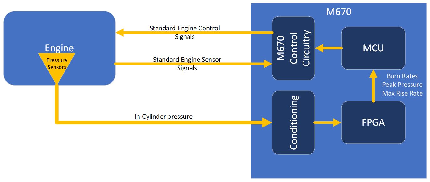
M670 with FPGA for in-cylinder pressure measurement
To provide the control performance required for GCI the system must measure the engine combustion characteristics each cycle in order to compensate the outputs used in the next cycle. Aramco Services Company determined that to have enough control for the GCI engine they needed the following in addition to the usual engine control algorithms used in production vehicles:
- Heat release curve crank degree vs. burn percentages
(crank angle of combustion for different percentages such as CA10, CA20, CA50, and CA90) - Max pressure rise rate and location (in crank degrees)
- Peak pressure value and location (in crank degrees)
To perform these calculations fast enough in an FPGA to meet 0.1 degree resolution at high RPM requires an intricate understanding of FPGA operations, and how leverage those to efficiently perform calculations. For maximum pressure rise rate and peak pressure these calculations are relatively easily implemented in a few FPGA clock cycles, however the heat release calculation is much more challenging since it is a function of pressure and crank angle over time.
The heat released to the piston can be approximated by:
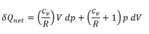
The two terms on the right represent the sensible energy change and work transfer to the piston.
The net heat-release profile obtained from integrating the first two terms on the right-hand side of the above equation, normalized to give unity at its maximum value, is often interpreted as the burned mass fraction (or, more correctly, the energy-release fraction) versus crank angle profile.
Use of the above equation, requires a value of Cv/R = [1/γ-1]. The ratio of specific heats γ for both unburned and burned gases decreases with increasing temperature and varies with composition. An approximate approach, modelling γ(T) with a linear function of temperature fitted to the appropriate curves and with γ constant during combustion, has been shown to give adequate results.
The heat release rate can be calculated by:

From the slider crank model, we have a definition for cylinder volume, V:
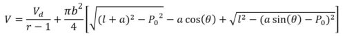
Taking the derivative w.r.t crank angle θ,
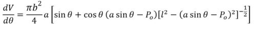
This calculation can be done in an FPGA using multiple steps and look up tables for the SIN and COSINE functions, but if we let
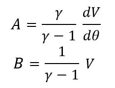
The equation becomes:
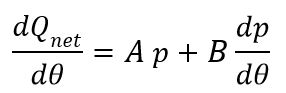
Which can be simplified for computation to:
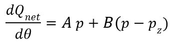
Using this equation, A and B can be pre-computed for a given engine and stored in a table for access on each 0.1 crank degree. The real-time calculation is simplified to provide a few high-speed calculations using quick accesses to the stored data, and the latest sample from an analog to digital converter. To provide the crank angles of combustion (such as CA50) a simple search algorithm is applied at the end of the cylinder cycle. This search algorithm can be completed in few FPGA clock cycles before the next cylinder cycle starts.
Implementation
Utilizing the internal scalability of the M670, Dana developed a daughter board with analog signal acquisition and a Field Programmable Gate Array (FPGA), to acquire signals such as the internal cylinder pressure to quickly perform the required in-cylinder pressure calculations. An FPGA capable of meeting the requirements had to be selected, and Dana chose the Intel MAX10M50 FPGA. As Intel describes, the MAX 10 FPGAs offer system-level cost savings through increased integration of system component functions:
- Dual configuration flash—A single, on-die flash memory supports dual configuration, for true fail-safe upgrades with thousands of possible reprogram cycles.
- Analog blocks—Integrated analog blocks with ADCs and temperature sensor provide lower latency and reduced board space with more flexible sample-sequencing.
- Instant on—MAX 10 FPGAs can be the first usable device on a system board to control bring-up of other components such as high-density FPGAs, ASICs, ASSPs, and processors.
- Nios® II soft core embedded processor—MAX 10 FPGAs support the integration of the soft core Nios II embedded processors, providing embedded developers a single-chip, fully configurable, instant-on processor subsystem.
- DSP blocks—As the first non-volatile FPGA with DSP, MAX 10 FPGAs are ideal for high-performance, high-precision applications using 144 integrated 18×18 multipliers.
- DDR3 external memory interfaces—MAX 10 FPGAs support DDR3 SDRAM and LPDDR2 interfaces through soft intellectual property (IP) memory controllers, optimal for video, datapath, and embedded applications.
- Complex control management—Software-controlled system management through Nios II soft core embedded processors
- Single-core voltage support—Single supply offering required for power-up sequence management
- User flash—With up to 736 KB of on-die user flash code storage, MAX 10 FPGAs enable advanced single chip Nios II embedded applications. The amount of user flash available depends on configuration options.
Additionally, the M670 FPGA daughter board provides these features external to the MAX10M50:
- Additional flash—64MByte of additional QSPI user flash available for data storage.
- DDR2 SDRAM—64MByte of DDR2 RAM for storage of data including calculation results and logged inputs (custom built option)
- External Inputs—10 External Inputs which can be digital or analog signals with signal conditioning
- External Outputs—two low side outputs connected to the M670 external connector allow functions external to the M670 to be triggered (if not necessary these can be converted to additional analog inputs)
- Fast clock— Up to 100MHz internal FPGA clock
Utilizing the internal ADC of the MAX10M50 provides the ability to acquire cylinder pressure samples synchronized to the engine crank, where an external ADC would result in additional delays between crank angle and ADC data. The one clock access to the UFM memory allows the calculation to be performed quickly, before storing the results in a table in the embedded memory blocks. Since multi-cylinder engines often have overlapping cylinder cycles, the dual ADC structure of the MAX10M50 is utilized to simultaneously process two cylinders including V8 or V6 engines.
The results of the calculation obtained at the end of each cylinder cycle are read by the M670 controller through a high-speed SPI interface. These results are then used by Aramco Services Company’s complex control strategy to modify the fueling and timing for the next cycle for that cylinder.
Results and Impact
Requirements of Aramco Services Company to develop complex combustion driven strategies for efficient engine management was fulfilled through the addition of an FPGA based daughter card to the M670. Aramco Services Company has thus been able to develop their GCI engine technology resulting in improved engine efficiency. Dana’s expertise in custom electronics, engine management and combustion fundamentals allowed the development of this innovative solution.
The speed of the FPGA provides the acquisition and calculation of results for each cylinder angle at a rate of 0.1 degree up to 8,000 RPM. Once a cylinder cycle completes the FPGA determines the location of the configured burn angles in less than 125uS which is less than 6 degrees of crank rotation at 8,000 RPM. This allows the M670 processor to adjust the control strategy to match the current performance of each cylinder before the fuel injection for the next cycle is begun. With this, the customer was able to develop strategies to provide more efficient combustion every cycle, with lower variation between cycles.
By utilizing an FPGA, the calculation required can be tailored to the engine immediately by changing the calculation parameters, or changed completely by downloading new FPGA code. An example of this is the case where the crank angle at which 50% of the fuel is burned is later than the optimum angle. In this case, before the next cycle the ignition time can be moved earlier of the fuel injected to achieve optimum combustion.
Project Features
Control and Application Software
FPGA flexibility and upgradability
 Accessibility