
A Review of Some Charging Standards
Electric vehicles (EVs), such as battery electric vehicles or plug-in hybrid electric vehicles, are expected to take over a major part of the transportation sector. As a result, the demand for Electric Vehicle Supply Equipment (EVSE), also known as Charging Stations, is growing. An EVSE should be able to handle the charging process for different types of EVs. In addition, different EVs might have different charging requirements, in terms of charging power, charging time, AC/DC charging, etc. Therefore, several standards have been created to regulate the EV-EVSE interface and the charging process requirements.
DIN 70121 is one of the first standards that was developed to regulate the EV-EVSE interface. However, it lacked some features such as Transport Layer Security. Later, other standards, such as ISO 15118 and SAE standards were developed based on DIN 70121 to regulate secure charging requirements in an EV-EVSE interface. Whereas SAE standards are more favorable in North America, ISO 15118 is the preferred standard in Europe. Both SAE J2847-2 and ISO 15118-2 have adopted the Power-Line Communication (PLC) physical layer for communications between EV and EVSE, however, there are some differences in the datalink layers of these two protocols.
EVSEs are capable of both DC and AC charging, as shown in Figure 1. In AC charging, the EV must be equipped with an onboard rectifier. The communication between EV and EVSE in AC charging is through a PWM signal over the Control Pilot signal. DC charging, however, has some benefits over AC charging. In DC charging, the onboard rectifier is no longer needed. In addition, much more electric power can be transferred in one DC charging session which reduces the charging session time in comparison with AC charging. However, due to the complexity of a DC charging session and billing requirements, a more advanced communication protocol than PWM communication is needed.
The following figure represents the physical interface between the EV and EVSE, based on J1772.
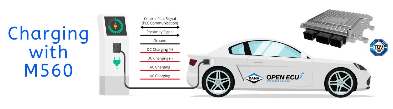
Figure 1 Combined Charging System (CCS) with OpenECU M560 or M580
A standard handshaking protocol is required by the Pilot and Proximity signals in the EV-EVSE interface. In addition, digital communication may take place between the EV and EVSE to initiate or terminate the electric energy transfer to the EV. This communication happens over the Control Pilot signal using the PLC protocol outlined in HomePlug Green PHY specifications. Although PLC for AC charging is optional, it is required for DC charging. SAE and ISO 15118 have both adopted the HomePlug Green PHY specification for PLC and have developed several standards to manage the digital communication in an EV-EVSE interface. Dana’s OpenECU M560 and M580 controllers support these standards and are compatible with HomePlug Green PHY specifications. To achieve this goal, the M560 and M580 are equipped with the Qualcomm Powerline Communication (PLC) chipset to support digital communication between the EV and EVSE over the Control Pilot signal. Furthermore, a library of supported Simulink blocks based on SAE J2847-2 and ISO 15118-2 are offered in the OpenECU development toolchain to manage the PLC communication in Simulink environment.
OpenECU M560 and M580 are ECUs designed for complex hybrid and EV applications, such as supervisory controller or battery management system. In AC charging, typically the onboard charger controller handles the EVSE interface. However, for DC charging, no onboard charger (rectifier) is required to be installed in the vehicle. Hence, the task of handling the EVSE interface and managing the charging session is assigned to another ECU in the vehicle, such as the supervisory controller. M560 and M580 are designed to be compatible with DC charging requirements in accordance with SAE and ISO 15118 standards.
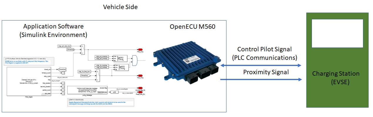
Figure 2 M560/M580 interface to EVSE
According to HomePlug Green PHY PEV-EVS, once an EV is connected to the EVSE, an association protocol assigns that EVSE to the EV. This procedure is handled via SLAC Association on Pilot signal as described in Green PHY PEV-EVS and SAE J2931-4 (or ISO 15118). For SAE J2931-4, OpenECU M560/M580 handles the SLAC protocol in its platform (base) software. However, for ISO 15118, the SLAC protocol needs to be implemented in application software, as needed for the protocol, using the Simulink blocks provided by the OpenECU platform software.
Currently in North America, SAE J1772 defines the most common protocol for establishing communication and configuring charging session parameters for the EV-EVSE interface, but in Europe ISO 15118 is the dominant standard. In both standards, once an EVSE is associated with the EV with SLAC protocol, several sequential stages must take place over PLC communication for configuring the charging parameters, and managing the energy flow to the EV:
- Initialization of the charging session
- Isolation monitoring and pre-charge
- Energy transfer
- Shutdown and disconnect
OpenECU M560 and M580 Support for Interfacing With EVSE
M560 and M580 are designed to handle AC or DC charging sessions. The hardware provides the electrical and communications interfaces, and the OpenECU platform software provides the hooks into those hardware elements to implement whichever charging protocol the application software requires. The OpenECU platform offers the two Simulink blocks depicted in Figure 3 to access the physical and data-link layers of the PLC protocol as needed, for either SAE 1772 or ISO 15118-3. These two Simulink blocks are for handling the data exchange between the OpenECU M560/M580 (EV side) and an off-board DC charger (EVSE side). The application software can be customized as needed for implementing either one of SAE J2847-2 or ISO 15118-2 protocols for handling a charge session, based on Simulink blocks in Figure 3.
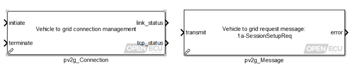
Figure 3: Two Simulink blocks are provided for M560/M580 to handle a full DC charging session. The block ‘pv2g_Connection’ establishes the EV-EVSE communication link via SLAC protocol. The block ‘pv2g_Message’ is configurable and updates its ports based on selected message to be sent or received to/from the EVSE.
At the beginning of a DC charging session, an EVSE must be associated with the EV that is connected to it. Only then, a local communication network can be established between the EV and the EVSE. The association of EVSE and EV is handled by Signal Level Attenuation Characterization (SLAC) protocol. The OpenECU platform software offers a Simulink block that handles the entire SLAC protocol based on SAE J2931/4, as shown in Figure 4. The Simulink application software needs to trigger (initiate) this block once the Pilot signal is detected on the M560/M580 dedicated pin for the Pilot wire. In the future, Dana plans to provide Simulink blocks so that the SLAC protocol can be customized as needed by the Application software. After establishing the communication link with the EVSE, the block outputs may be used to notify the application control software. As was mentioned previously, please note that the SLAC protocol for ISO 15118-2 needs to be implemented in application control software using OpenECU dedicated Simulink blocks.
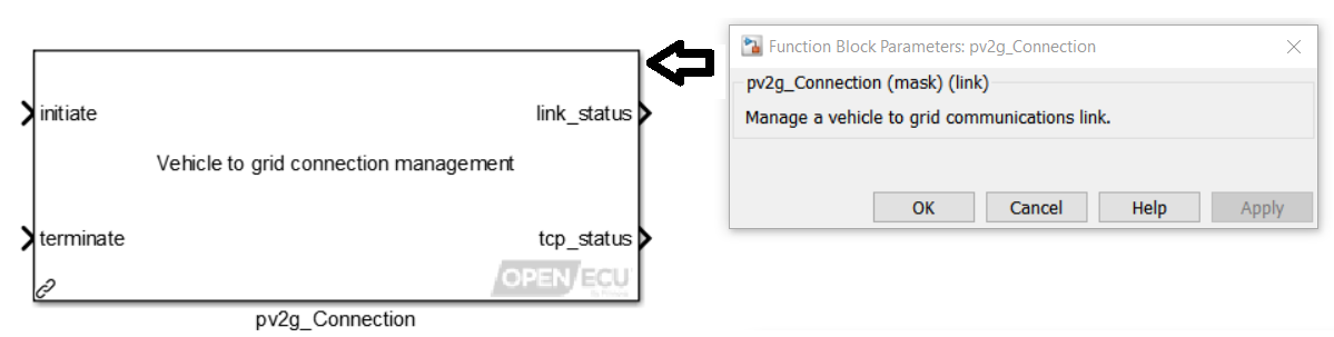
Figure 4: Simulink block that handles the SLAC protocol and sets up the communication link with the DC charger between EV and EVSE. The entire SLAC protocol is handled by the OpenECU platform software.
Once an EV-EVSE association and communication link is successfully established, the DC charging session begins where a continuous data exchange is required between the EV and the EVSE over the PLC interface. A normal DC charging session requires several sequential stages to be completed (For instance, see SAE-J1772 F.1.8 and F.1.9 for Normal Startup and Shutdown Sequences). The OpenECU platform provides a configurable Simulink block to handle these stages at the application layer of PLC communications, as outlined in SAE J2847-2 or ISO 15118-2. For example, Figure 5 represents two different configurations of this block for transmitting two messages during initialization stage.
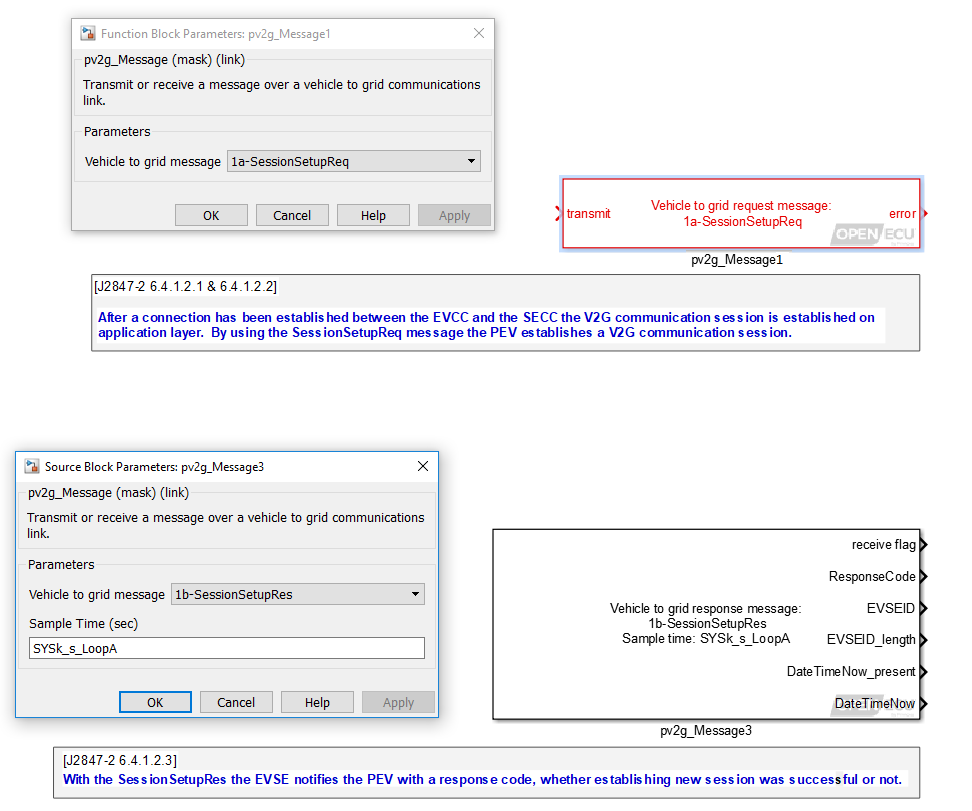
Figure 5: Configurable Simulink blocks (based on SAE J2847-2) supported by OpenECU platform to manage message transmit/receive over the PLC communication in an EV-EVSE interface. The block inputs and outputs are configured automatically based on the standard for the selected message. The same blocks can be used for implementing ISO 15118 protocol.
The Simulink block in Figure 5 is fully compatible with SAE J2847-2 and ISO 15118-2 and facilitates the message transmit/receive over the PLC interface. This Simulink block can be used to implement the required stages of SAE J1772 or ISO 15118-2 in the Simulink environment for the M560/M580. If needed, Dana can provide support for implementing all of the SAE J1772 or ISO 15118-2 stages in Simulink.
 Accessibility