
Dana was responsible for delivering a complete BLDC design including hardware and software for a motor used in an HVAC application. The scope of the program included a full design package, Design Failure Mode and Effect Analysis (DFMEA) and completed Design Verification Plan & Report (DVP&R). The timeline for the project was 10 months from project kickoff to completion of project deliverables.
The design must:
- Fit into the customer designed mechanical assembly
- Operate on either a 12 V system or a 24 V system
- Drive a sensor-less 12V or 24V motor based on a speed signal
- Operate between -40°C to +85°C ambient conditions
- Meet Electromagnetic Compatibility (EMC) requirements based on CISPR 25
Background
Brushless DC motors have to be electrically commutated by a controller. There are two common methods for doing this: trapezoidal and sinusoidal.
Figure 1 below shows a comparison of trapezoidal and sinusoidal control methods. The motor phase currents are in blue, high side motor field effect transistors (FETs) are in red, low side FETs are in green. Current flows through a motor phase when either its high side FET is on while the low side FET of another motor phase is on, or when its low side FET is on while the high side FET of another phase is on. The pair of FETs for a motor phase can never both be on at the same time.
Trapezoidal control breaks the electrical commutation cycle into 6 steps. Each step sequentially controls current through two motor phases, leaving the third phase open. Trapezoidal control only requires one FET to be Pulse Width Modulated (PWMed) at a time, all the other FETs are either open or closed for the entire commutation step. Each commutation step is 60 degrees, and each motor phase is separated by 120 degrees from the others.
Sinusoidal control continuously varies the PWM duty cycle of all three motor phases to achieve a sinusoidal current waveform through each phase. As in trapezoidal control, the three phases are offset by 120 degrees from each other. Since current needs to be controlled continuously in all three phases, complimentary PWM switching is required. With this scheme, the low and high side FET pairs are always in opposite states so that for each motor phase, there is always one FET on.
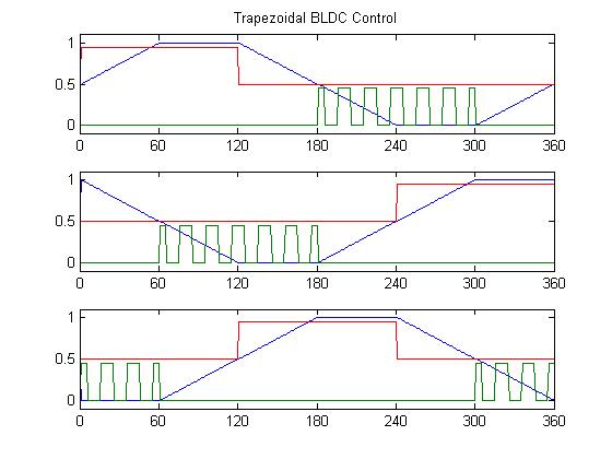
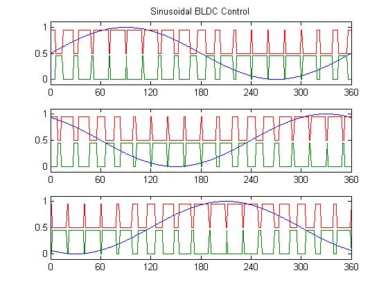
Figure 1 – Comparison of Trapezoidal vs. Sinusoidal BLDC control
In order to control a BLDC motor, the rotor position must be known. Hall-effect sensors are one of the most common methods for measuring position, typically with three sensors configured to provide a resolution of 60 degrees. There are also many different types of encoders which can provide very high resolution. These sensors can add cost and hardware complexity. The sensors can be eliminated by using software to estimate the rotor position from the back electromotive force (EMF) of the motor. While this reduces hardware complexity, it adds significantly to the software complexity. Accurate knowledge of the motor’s characteristics is required in order to estimate the rotor position.
One of the biggest challenges of BLDC motor control is startup. Before the motor starts spinning, the load is unknown, and in the case of a sensorless system, the rotor position is also unknown.
Architecture Approach
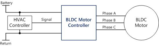
The high level system diagram is shown in Figure 2. The main priority of the BLDC design was three phase motor control.
Application specific integrated circuits (ASICs) were available at the beginning of the project for sensorless BLDC control. The DRV10983 is a good example of one, though it lacked both voltage rating and current capability. Discrete implementations allow the flexibility to choose all the components for specific voltage and current ratings. The discrete implementation of the sensorless control is done by a microcontroller. A pre-driver converts logic level commands into gate drives for MOSFETs or insulated gate bipolar transistors (IGBTs). Voltage and current signals from each phase is fed back into the microcontroller to complete the control loop.
The quick timing nature of the program did not allow enough time to develop the sensor-less control strategy from scratch. A review of the available motor control strategies determined that InstaSPIN was the most robust motor control development platform for the intended application.

Figure 2 – High Level System Diagram
BLDC Design Challenges
Packaging
Due to high power and small size constraints of the PCB assembly it was crucial that several details of the design were well communicated.
- Locations of phase connections between the motor and PCB
- PCB mounting locations
- Areas of the PCB that needed to have a heat sink
- Placement of large components such as filter capacitors and inductors
- Power and signal in connections
12v or 24v System
Early in the design phase it was realized that it was not possible to achieve low cost high performance goals with a single component population. For example, an ideal 24V motor would only need 10A to achieve 240W output power. An ideal 12V motor would need 20A to achieve the same output power. A single design for both motors would require higher voltage components for the 24V motor, but the same components would need to be capable of the current to operate the 12V motor.
Tradeoffs when choosing components to meet specific properties are shown in Table 1. Ripple currents in the 12V system are twice as much as the 24V system, requiring the capacitance to be twice as much. Capacitors with the voltage rated for the 24V system, but capacitance enough for the 12V system, would have forced a large increase in the size of the mechanical package. The MOSFETs for the 12V system needed to switch twice the current as in 24V system. Based on Ohm’s Law, P = I2R, utilizing the same MOSFETs in both systems would mean the 12V system would generate 4 times as much heat as the 24V system. The same heat generation applies to the inductor too. These factors would make the design much bigger and require more heat to be dissipated.
| Component Type | Constraints | Changes of Relative Properties |
| MOSFET | Package, Cost | VDS ↑, RDS-ON ↑, ID ↓ |
| Capacitor | Size | V ↑, C ↓, ESR ↑, IRipple ↓ |
| Inductor | Size | L ↑, R ↑, I ↓ |
Table 1- Tradeoff of Component Properties
The solution was an architecture that used a single PCB and different populations for each system voltage. This required the packages of the components selected for each voltage to be identical. The blue colored blocks in Figure 3 depict the components that were changed between the two system voltages. This solution allowed building one PCB design with two populations on the same manufacturing line while providing 90% commonality between the two systems.
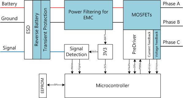
Figure 3 – Hardware Architecture of Varied Components
Electro-Magnetic Compatibility
Early in validation testing it was understood that conducted emissions testing was going to be challenging for this high power design. A spectrum analyzer was used to allow the team time to study the design in the frequency domain and look for sources of the emissions. Line Impedance Stabilization Networks (LISNs) were built and the CISPR 25 test setup was created at Dana. The test results matched within a dB between the new test setup and the data recorded at the test facility, providing a high level of confidence in the testing.
There were two major improvements that contributed to the success of the final design. The first was a HW adjustment to the main DC filter that improved the noise suppression in the lower frequencies of interest. The second improvement was aimed at removing the 20 kHz reflections from the motor drive PWMs.
The frequency domain sweeps showed the filter was not very effective at removing frequency between 400 kHz and 800 kHz. Adjusting the copper length between components on the PCB showed that the layout made a significant difference. Figure 4 shows the main components of the filter labeled C1, C2, and L1. Switching noise on the inverter ground was coupling through C1 of the filter. Moving the ground of C1 further from C2 and the inverter ground in the PCB layout created enough parasitic inductance to block that noise and keep it off the power line.

Figure 4 – Introducing Parasitic Inductance
The 20 kHz reflections were removed by modulating the PWM switching frequency instead of using a constant 20 kHz. We were able to vary the frequency between 18 and 22 kHz without affecting the motor control. This allows the energy to be distributed across a wider frequency range, which greatly reduces the amplitude peaks shown in the spectrum analyzer plot in Figure 6. Since there are an infinite number of ways to modulate the frequency, we used Matlab to plot histograms and quickly compare various designs. Figure 5 shows a histogram comparison of several methods we tested. The average frequency has to be 20 kHz, and the best emissions results occur when the frequency is spread evenly across as many different values as possible.
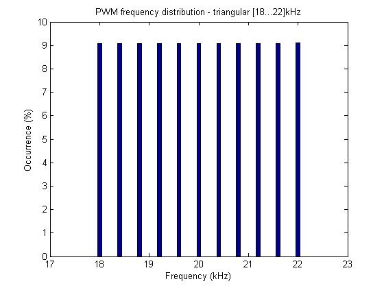
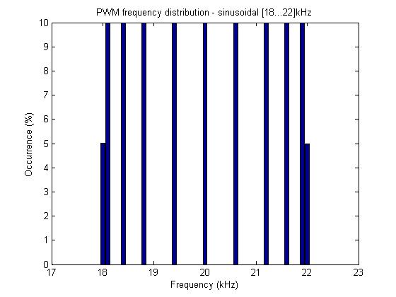
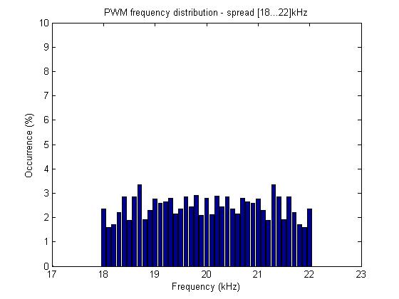
Figure 5 – Histogram Comparison of PWM Frequencies
Top: original configuration using constant 20kHz
Top Middle: sinusoidal distribution across [18…22]kHz
Bottom Middle: triangular distribution across [18…22]kHz
Bottom: final distribution method across [18…22]kHz
Figure 6 shows a 10 dBuV improvement after implementing both of those changes.
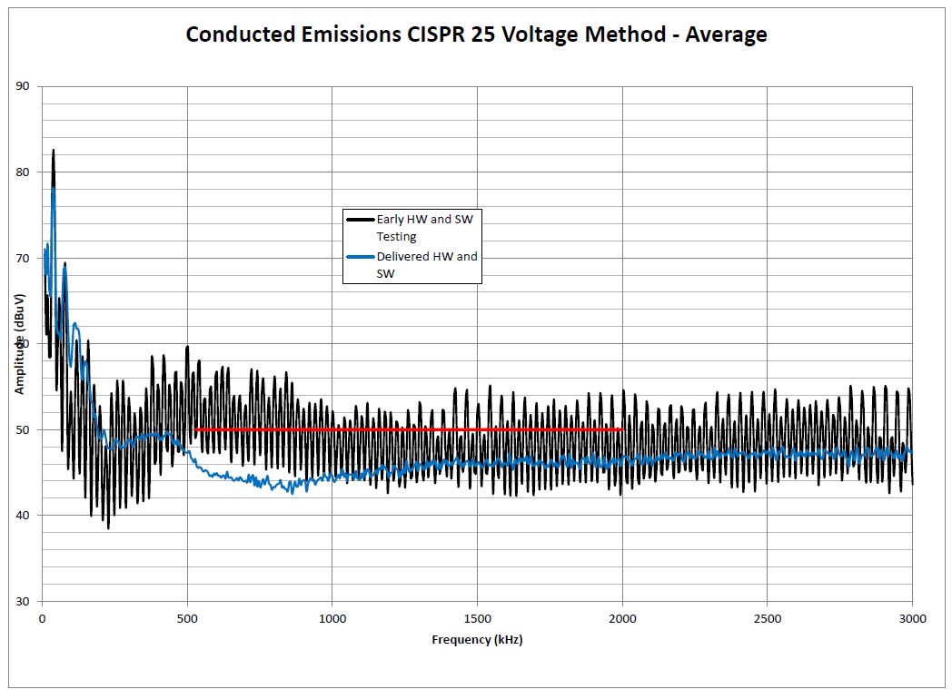
Figure 6 – CISPR 25 Conducted Emissions Improvements
Startup Robustness
As mentioned above, motor startup is one of the most challenging parts of a BLDC design. The InstaSPINTM estimator needs several motor parameters to accurately estimate the rotor position. One of the most critical for startup is stator resistance (Rs). We found that there was enough variation among the motors that the Rs value had to be calibrated for each motor and controller assembly. To do this, we implemented a strategy to run the Rs identification routine on the very first motor startup, and store the value to non-volatile memory. On subsequent startups, the stored value is used. Additionally, the Rs value can change significantly with temperature. To account for this, the value is normalized for temperature at the time it is calibrated. At startup time, the stored value is then adjusted for the operating temperature.
Summary
The BLDC design was a project with several unknowns and demanding design criteria. Dividing the design into two populations to solve the dual voltage system requirements was a decision that avoided cost and size problems later in the program. Some unknowns, such as EMC and startup robustness, were more challenging than others and more time was allocated to refine the design in those areas. The result was a cost effective and robust BLDC motor controller hardware and software design solution that met and exceeded expectations.
 Accessibility