
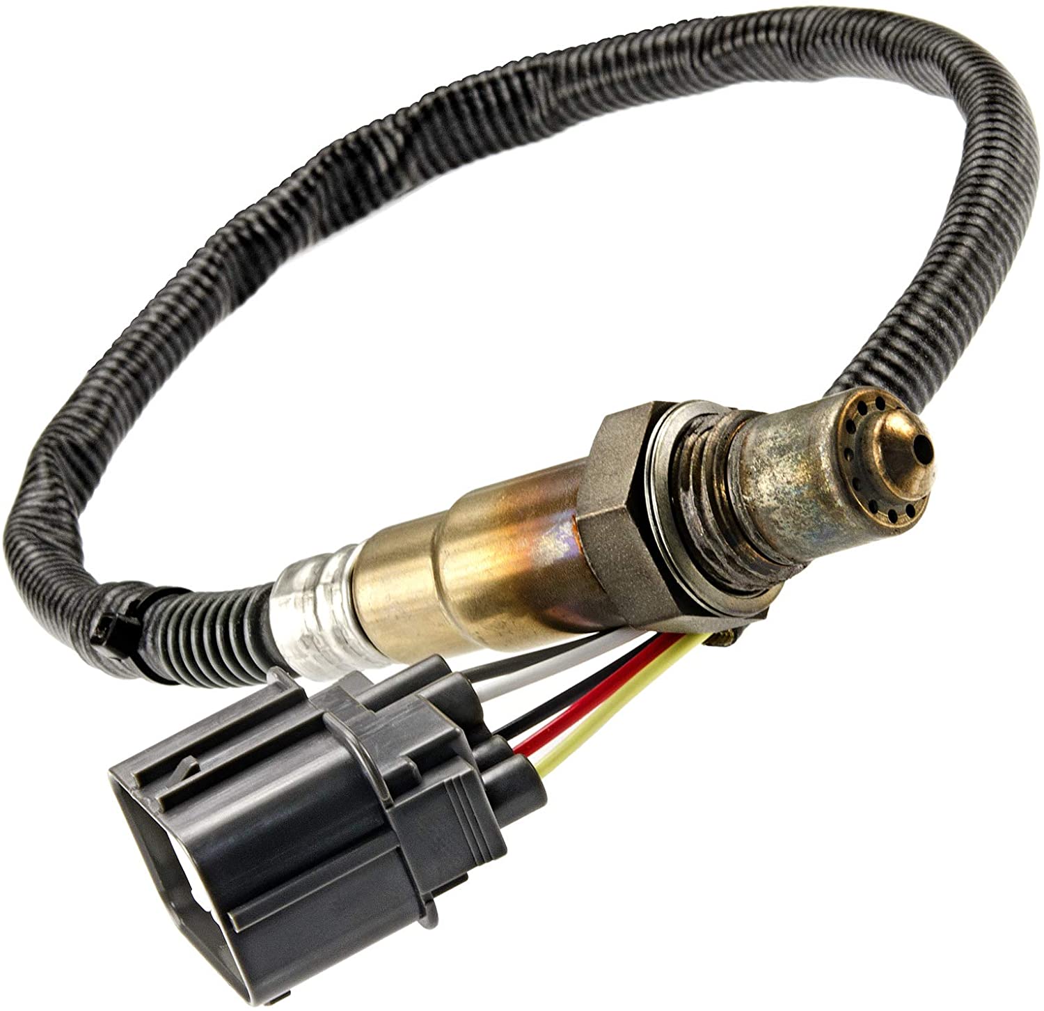
Modern engine controls are increasingly using wide band lambda sensors for air/fuel measurement feedback. These wideband oxygen sensors offer a typical range of 0.65 to 2.0 lambda as compared to the narrow operational range of a conventional oxygen sensor. These wide band sensors require dedicated integrated circuits to operate and cannot be read with basic analog input circuits like switching oxygen sensors. The implementation of a circuit to read a Bosch LSU 4.9 wideband oxygen sensor is described as well as the software required to interface with the circuit.
The Bosch LSU 4.9 sensor is paired with a Bosch CJ125 integrated circuit. The CJ125 provides many of the low level control, diagnostic, and configuration to read the LSU 4.9 sensor. The CJ125 is configured via a SPI (serial protocol interface) by a microcontroller. The CJ125 provides several key features for the control and measurement of the LSU 4.9 sensor.
Software Control of the LSU 4.9
Now let’s look at reading and controlling the Bosch LSU 4.9 using a Dana M670 ECU. OpenECU provides a Mathworks Simulink blockset to interface with the CJ125. These Simulink blocks handle all of the SPI communication to the CJ125 chip and provide the analog outputs from the sensor itself.
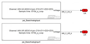
Converting voltage for UA and UR
The voltages UA and UR provided by the CJ125 is read using an analog input, as shown below, and is filtered for any noise present. The voltages are then converted to engineering values using individual look up tables.
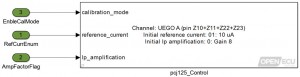
Read/Write SPI registers
The SPI interface makes it possible for the CJ125 and the microcontroller to communicate. Hence it is important that the microcontroller has the ability to read/write the registers on CJ125. For example: sensor line faults are written by the IC to certain registers which can be accessed by the microcontroller. Similarly the CJ125 needs to be stated if calibration mode for the sensor is enabled, provide reference current and amplification factor for computation of UA and UR. This can be handled as shown in the following image.
Temperature Control
It is important to maintain the temperature of the sensor at ~750oC for accurate lambda values. It is therefore important to have a suitable heater control strategy with feedback provided by the sensor temperature. To manage the heater circuit current draw it is best to vary the frequency of the PWM until the sensor is at operating temperature. Once the sensor is fully warm the frequency of PWM can be as low as 100 Hz, however when cold the frequency can initialize to ~10,000 Hz.
Note: The sensor temperature transfer function is nonlinear from room temp to ~650oC and linear from 650 oC and above. Hence in conditions where the sensor is starting from below ambient temperature (<-10oC) one may have to employ an open loop strategy until the sensor temperature can be read and switched over to a closed loop strategy.
Results
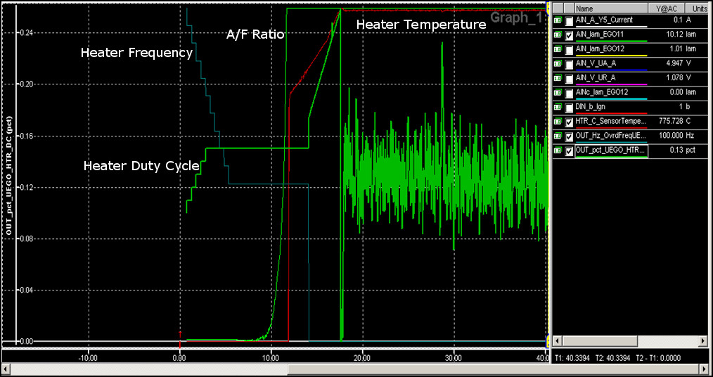
Shown below is the high level heater control strategy and lambda value read from the LSU 4.9 using Simulink in OpenECU.
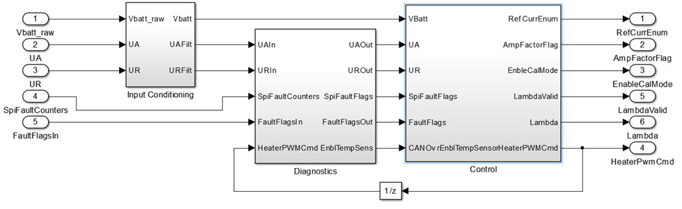
The LSU 4.9 was controlled using the above software on an M670, with a start temperature of -40oC in free air(~λ = 10). Fig 4 shows the results captured in ATI vision. It is observed that until a valid sensor temperature can be read the heater is controlled in an open loop strategy.
 Accessibility