

 The Dana team has extensive experience in developing EV control strategies. Based on customer’s needs, Dana can provide a custom solution or a ready to use baseline EV control application software that can be used with the OpenECU™ M560 and M580 embedded controllers. The M560 and M580 controllers have been certified by TUV SUD for use as safety elements out of context in conjunction with the OpenECU-FS base software to satisfy safety goals rated up to ASIL D.
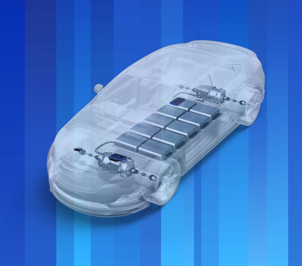
Following is a high-level overview of the software IP for EV supervisory control. The software is intended for use with Battery Electric Vehicles and customers can quickly get their vehicle up and running, reducing the lead time for application development significantly.
Feature highlights:
- Traction motor control (via CAN commands. single motor)
- Transmission Control
- Thermal Management
- Mitigation actions – (Implements functional safety mechanisms)
- Interface with Driver Display Unit/HMI
- Control of Front and Rear Lights, Reverse Beeper
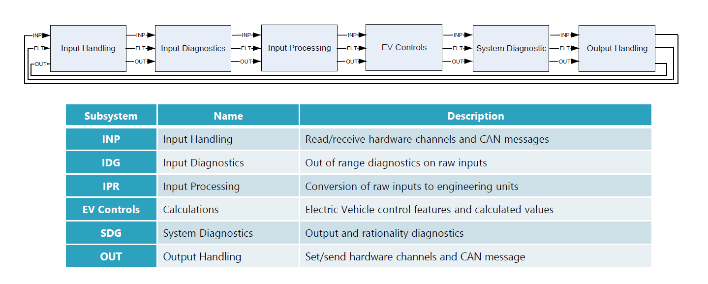
The core control logic of the EV control strategy has been developed with native Simulink blocks and hence it’ll be easier to switch to different hardware targets with minimal development effort. Based on the architecture diagram, OpenECU specific driver blocks are present only in the “Input Handling” and “Output handling” subsystems.
The EV control supervisor interacts with the following modules on CAN –
- Motor Control Module (A slave device which receives commands from VCU and controls the traction motor)
- Battery Management System (BMS)
- Autonomy interface (Autonomy commands sent from a wireless device are received via CAN on the VCU)
- Driver display interface.
- Charging Control interface
- Electronic Brake Control module
With the default configuration, the EV supervisor can command and control a single traction motor via CAN. The software can be enhanced if additional motors are required to be controlled.
The EV supervisory software also takes off-road applications into consideration. It can directly control two gearboxes as part of transmission control – the main gearbox and the mid-gearbox. Based on gear position inputs and mode selection inputs from the driver, the Transmission Control subsystem sets the driver requested gear by engaging the two gearboxes.
Thermal management is implemented by incorporating a bang-bang control scheme for coolant pump and the coolant fan when the temperature of the motor and inverter electronics exceeds a calibratable threshold.
The Mitigation Actions Subsystem implements a limited set of functional safety mechanisms. The two main unsafe situations addressed are – unintended acceleration and unintended direction of motion. Remedial action is taken are
- limiting the maximum drive torque
- Commanding the Brake Controller
The specific safety goals for your application can be different and will depend on the safety case and ASIL goals. Please contact Dana for more information on this topic.
Deliverables
A calibration guide which gives instructions on deploying and calibrating the system is provided along with the Simulink control strategy. Detailed descriptions of system features and calibration methods are included. Although the strategy is built using Simulink and Stateflow blocks and can be integrated in all types of platforms, the guide also provides instruction on how to implement the strategy using the OpenECU platform.
 Accessibility