
By using digital communication, many sources of inaccuracies are eliminated as compared with traditional analog sensors, such as wiring resistance, circuit component tolerances, and A/D conversion gain and non-linearity errors. Furthermore, more data can be placed on a single wire thus co-located such as manifold air flow and ambient air temperature sensors can use a single wire, thus saving on wiring harness costs.
One method of communication that is gaining popularity within engine sensors is SENT, also known as SAE J2716. SENT stands for Single Edge Nibble Transmission protocol. SENT uses the time between consecutive falling edges of a digital signal to encode a single nibble (4 bits) of data, where the longest time between falling edges represents binary 1111 (hex 0xF), and the shortest time between falling edges represents zero.
By encoding the nibbles using time, this allows for a high rate of data transmission at a lower cost than traditional serial communication.
Decoding a SENT signal
SENT messages typically have six data nibbles, allowing 24-bits of information to be transmitted per message. It is common to have two 12-bit signals encoded in each message. For example, an atmospheric temperature and pressure sensor may send the temperature in the first 3 nibbles, and the pressure in the second three nibbles. The 24-bit message will then need to be split apart into the two signals using bitwise arithmetic.
In addition to the 6 data nibbles, messages contain a synchronization pulse, one nibble for status and communication information, and one nibble for CRC error detection. The synchronization pulse is used by the receiver to calculate the exact bit-timing of the sender, thus making the system tolerant to small clock frequency differences between the sender and receiver.
SENT communication with OpenECU
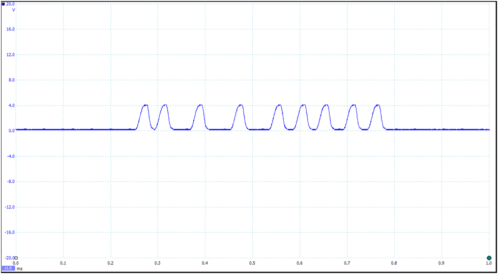
To show how SENT sensors are handled with OpenECU, we will use a throttle position sensor from a modern production engine. Our sensor uses all 24 data bits of the SENT message to encode the throttle position, and communicates with a nominal communication tick duration of 3.4 microseconds. A typical message waveform from our throttle position sensor is shown in the following oscilloscope capture:
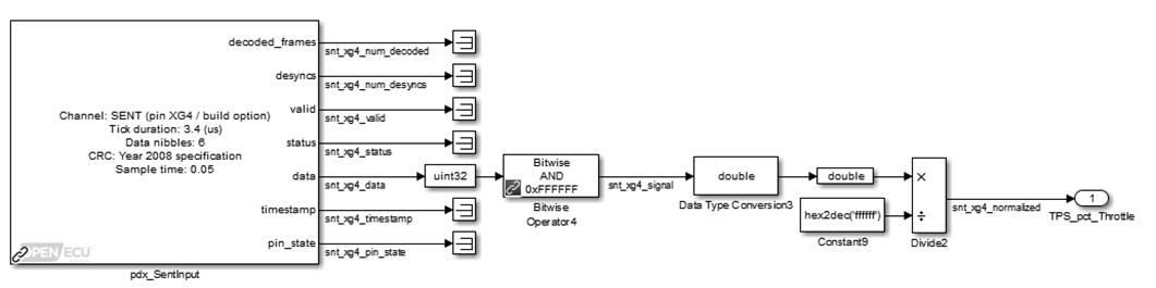
The OpenECU Blockset for M670 contains a SENT input block which handles all of the decoding of the SENT messages, including CRC checking and synchronization. In our example, we extract the 24-bits of signal information, and convert the signal to a 0.0 – 1.0 number to represent throttle fraction:
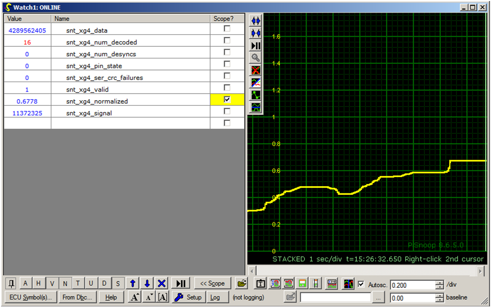
After building the model for the M670 and flashing the generated software onto an M670 ECU, the throttle position sensor could be easily viewed using a standard calibration tool. A signal trace showing the throttle position using OpenECU Calibrator can be seen below:
Further information on SENT, can be obtained through SAE in the J2716 standard document. A brief overview can be found on Wikipedia.
 Accessibility